1. The condensers of capacity \[C_{1}\] and \[C_{2}\] are connected in
parallel, then the equivalent capacitance is
a) \[C_{1} + C_{2}\]
b) \[\frac{C_{1}C_{2}}{C_{1}+C_{2}}\]
c) \[\frac{C_{1}}{C_{2}}\]
d) \[\frac{C_{2}}{C_{1}}\]
Explanation: \[C_{1} + C_{2}\]
2. A parallel plate capacitor is made by stacking n equally
spaced plates connected alternately. If the capacitance
between any two plates is C then the resultant capacitance
is
a) C
b) nC
c) \[\left(n -1\right)C\]
d) \[\left(n +1\right)C\]
Explanation: The given arrangement becomes an arrangement of (n - 1) capacitors connected in parallel. So CR = (n - 1)C
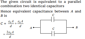
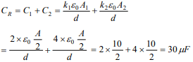
3.Four plates of equal area A are separated by equal
distances d and are arranged as shown in the figure. The
equivalent capacity is
a) \[\frac{2\epsilon_{0}A}{d}\]
b) \[\frac{3\epsilon_{0}A}{d}\]
c) \[\frac{5\epsilon_{0}A}{d}\]
d) \[\frac{\epsilon_{0}A}{d}\]
Explanation:
4.The capacitor of capacitance \[4\mu F\] and \[6\mu F\] are connected
in series. A potential difference of 500 volts applied to the
outer plates of the two capacitor system. Then the charge
on each capacitor is numerically
a) 6000 C
b) 1200 C
c) 1200 \[\mu C\]
d) 6000 \[\mu C\]
Explanation:
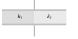
5. A parallel plate capacitor with air as medium between the
plates has a capacitance of 10 \[\mu F\] . The area of capacitor is
divided into two equal halves and filled with two media as
shown in the figure having dielectric constant \[k_{1}=2\] and \[k_{2}=4\] . The capacitance of the system will now be
a) 10 \[\mu F\]
b) 20 \[\mu F\]
c) 30 \[\mu F\]
d) 40 \[\mu F\]
Explanation:
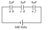
6.Three capacitors are connected to D.C source of 100 volts
shown in the adjoining figure. If the charge accumulated on
plates of \[C_{1},C_{2}\] and \[C_{3}\] are \[q_{a},q_{b},q_{c},q_{d},q_{e}\] and \[q_{f}\]
respectively, then
a) \[q_{b}+q_{d}+q_{f}=\frac{100}{9}C\]
b) \[q_{b}+q_{d}+q_{f}=0\]
c) \[q_{b}+q_{d}+q_{f}=50 C\]
d) \[q_{b}=q_{d}=q_{f}\]
Explanation: In series combination, charge is same on each capacitor.
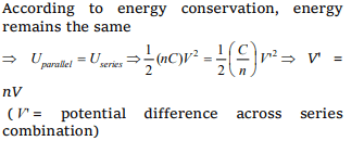
7. n identical condensers are joined in parallel and are
charged to potential V . Now they are separated and joined
in series. Then the total energy and potential difference of
the combination will be
a) Energy and potential difference remain same
b) Energy remains same and potential difference is nV
c) Energy increases n times and potential difference is nV
d) Energy increases n times and potential difference
remains same
Explanation:
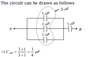
8. Three capacitors each of capacitance \[1\mu F\] are connected in
parallel. To this combination, a fourth capacitor of
capacitance \[1\mu F\] is connected in series. The resultant
capacitance of the system is
a) \[4\mu F\]
b) \[2\mu F\]
c) \[\frac{4}{3}\mu F\]
d) \[\frac{3}{4}\mu F\]
Explanation:
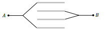
9. Five capacitors of \[10\mu F\] capacity each are connected to a
d.c. potential of 100 volts as shown in the adjoining figure.
The equivalent capacitance between the points A and B
will be equal to
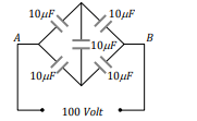
a) 40 \[\mu F\]
b) 20 \[\mu F\]
c) 30 \[\mu F\]
d) 10 \[\mu F\]
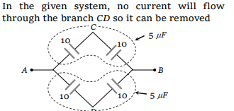
Explanation:
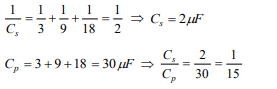
10.Three capacitors of capacitances \[3\mu F,9\mu F\] and \[18\mu F\] are
connected once in series and another time in parallel. The
ratio of equivalent capacitance in the two cases \[\left(\frac{C_{s}}{C_{p}}\right)\]
will
a) 1 : 15
b) 15 : 1
c) 1 : 1
d) 1 : 3
Explanation: