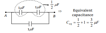
1. If three capacitors each of capacity \[1\mu F\] are connected in
such a way that the resultant capacity is \[1.5\mu F\] , then
a) All the three are connected in series
b) All the three are connected in parallel
c) Two of them are in parallel and connected in series to
the third
d) Two of them are in series and then connected in
parallel to the third
Explanation:
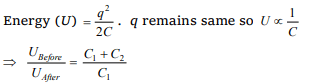
2. A capacitor of capacity \[C_{1}\] is charged to the potential of \[V_{0}\] .
On disconnecting with the battery, it is connected with a
capacitor of capacity \[C_{2}\] as shown in the adjoining figure.
The ratio of energies before and after the connection of
switch S will be
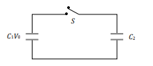
a) \[\left(C_{1}+C_{2}\right)/C_{1}\]
b) \[C_{1}/\left(C_{1}+C_{2}\right)\]
c) \[C_{1}C_{2}\]
d) \[C_{1}/C_{2}\]
Explanation:
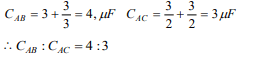
3.Four capacitors of each of capacity \[3\mu F\] are connected as
shown in the adjoining figure. The ratio of equivalent
capacitance between A and B and between A and C will
be

a) 4 : 3
b) 3 : 4
c) 2 : 3
d) 3 : 2
Explanation:
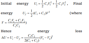
4. The capacities of two conductors are C1 and C2 and their
respective potentials are V1 and V2 . If they are connected by
a thin wire, then the loss of energy will be given by
a) \[\frac{C_{1}C_{2}\left(V_{1}+V_{2}\right)}{2\left(C_{1}+C_{2}\right)}\]
b) \[\frac{C_{1}C_{2}\left(V_{1}-V_{2}\right)}{2\left(C_{1}+C_{2}\right)}\]
c) \[\frac{C_{1}C_{2}\left(V_{1}-V_{2}\right)^{2}}{2\left(C_{1}+C_{2}\right)}\]
d) \[\frac{C_{1}C_{2}\left(V_{1}-V_{2}\right)}{C_{1}C_{2}}\]
Explanation:
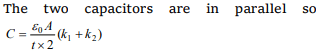
5. parallel plate condenser is filled with two dielectrics as
shown. Area of each plate is A \[metre^{2}\] and the separation
is t metre. The dielectric constants are \[k_{1}\] and \[k_{2}\]
respectively. Its capacitance in farad will be
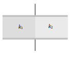
a) \[\frac{\epsilon_{0}A}{t}\left(k_{1} + k_{2}\right)\]
b) \[\frac{\epsilon_{0}A}{t}.\frac{k_{1} + k_{2}}{2}\]
c) \[\frac{2\epsilon_{0}A}{t}\left(k_{1} + k_{2}\right)\]
d) \[\frac{\epsilon_{0}A}{t}.\frac{k_{1} - k_{2}}{2}\]
Explanation:
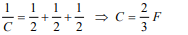
6.Three condensers each of capacitance 2F are put in series.
The resultant capacitance is
a) 6F
b) \[\frac{3}{2}F\]
c) \[\frac{2}{3}F\]
d) 5F
Explanation:
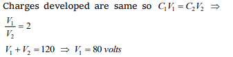
7. Two condensers of capacities \[1\mu F\] and \[2\mu F\] are connected
in series and the system is charged to 120 volts . Then the
P.D. on \[1\mu F\] capacitor (in volts) will be
a) 40
b) 60
c) 80
d) 120
Explanation:
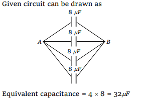
8. Four condensers are joined as shown in the adjoining
figure. The capacity of each is \[8\mu F\] . The equivalent capacity
between the points A and B will be
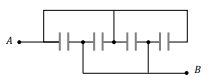
a) 32 \[\mu F\]
b) 2 \[\mu F\]
c) 8 \[\mu F\]
d) 16 \[\mu F\]
Explanation:
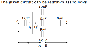
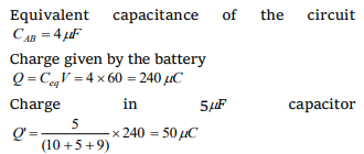
9. The capacities and connection of five capacitors are shown
in the adjoining figure. The potential difference between the
points A and B is 60 volts . Then the equivalent capacity
between A and B and the charge on 5 \[\mu F\] capacitance will
be respectively
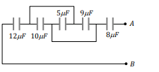
a) \[44\mu F,300\mu C\]
b) \[16\mu F,150\mu C\]
c) \[15\mu F,200\mu C\]
d) \[4\mu F,50\mu C\]
Explanation:
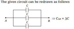
10. Three equal capacitors, each with capacitance C are
connected as shown in figure. Then the equivalent
capacitance between A and B is
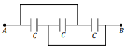
a) C
b) 3C
c) \[\frac{C}{3}\]
d) \[\frac{3C}{2}\]
Explanation: